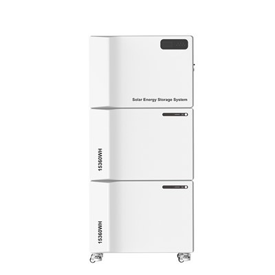


ALP Technology - Home Solar Energy Storage System
ALP home solar energy storage system refers to the storage of electricity locally by a home solar energy storage battery for later use. A home solar energy storage system consists of energy storage batteries, inverters, and other components. We use brand new A-grade LiFePo4 battery, equipped with an intelligent battery management system for charging and discharging cycles. The inverter converts DC energy to AC energy to meet the requirements for household electricity. Normally, this home energy storage battery is installed in combination with a PV system to provide green electricity to household users, reduce energy consumption, and reduce negative impacts on the environment, It's widely used in remote areas or areas with unstable power supply, to provide a reliable, stable, and cost-effective energy supply.

Product Parameters
|
Type |
ALP S-100 |
|
|
Inverter |
Rated power |
5.5kw; 11kw; 11kw |
|
AC rated voltage |
230VAC |
|
|
Rated frequency |
60Hz |
|
|
Efficiency |
≥98% |
|
|
Transfer time |
10ms |
|
|
Waveform |
Pure Sine wave |
|
|
Battery Overcharge |
58.4V |
|
|
Battery undervoltage alarm |
45V |
|
|
Constant voltage charge |
58.4V |
|
|
Float voltage |
56V |
|
|
Max charging current |
100A |
|
|
Communication interface |
RS232 (lnverter)/ RS485(BMS) |
|
|
Dimension |
70*26*51cm |
|
|
AC Input |
Norminal voltage |
230VAC |
|
Voltage range |
90-280VAC |
|
|
Rated frequency |
50/60Hz |
|
|
Frequency range |
40-70HZ |
|
|
Rated current |
30A; 60A; 60A |
|
|
Max AC current |
60A; 120A; 120A |
|
|
PV Input |
Max voltage |
500V |
|
Optimum voltage |
300-400V |
|
|
Voltage range |
120V-500VDC |
|
|
Max power |
5500W; 11000W; 11000W |
|
|
Rated capacity |
15360Wh(300Ah) 15360Wh(300Ah) 30720Wh(600Ah) |
|
|
Battery |
Norminal voltage |
51.2V |
|
Discharge voltage range |
43.2V-58.4V |
|
|
Standard charging current |
100A |
|
|
Max charging current |
200A |
|
|
Max discharging current |
200A |
|
|
Depth of discharge |
95% |
|
|
Communication interface |
CAN/IRS485 |
|
|
Cycle life |
≥6000, 25±2℃, 0.5℃, EOL80% |
|
|
Working temperature range |
Charge: 0℃-50℃; Discharge: -10℃-60℃ |
|
|
Storage temperature |
-10℃-60℃ |
|
|
Dimension |
70*26*51cm |
Product Dimension

Packing List

|
Name |
Item No |
Components |
CNT |
Carton Size |
N.W (kg) |
G.W (kg) |
Unit CBM (m3) |
Total CBM (m3) |
|
APOLLO C Series 15KWH |
SCAP-C-51.2-300 (5kW) |
Inverter |
1 |
75.8*56.3*31.6CM |
24.5 |
27 |
0.135 |
0.135 |
|
Battery |
1 |
76*60*42CM |
110.8 |
128.3 |
0.192 |
0.192 |
||
|
APOLLO C Series 15KWH |
SCAP-C-51.2-300 (10kW) |
Inverter |
1 |
75.8*56.3*31.6CM |
33 |
35 |
0.135 |
0.135 |
|
Battery |
1 |
76*60*42CM |
110.8 |
128.3 |
0.192 |
0.192 |
||
|
APOLLO C Series 30KWH |
SCAP-C-51.2-600 (10kW) |
Inverter |
1 |
75.8*56.3*31.6CM |
33 |
35 |
0.135 |
0.135 |
|
Battery |
2 |
76*60*42CM |
110.8 |
128.3 |
0.192 |
0.383 |
System Diagram

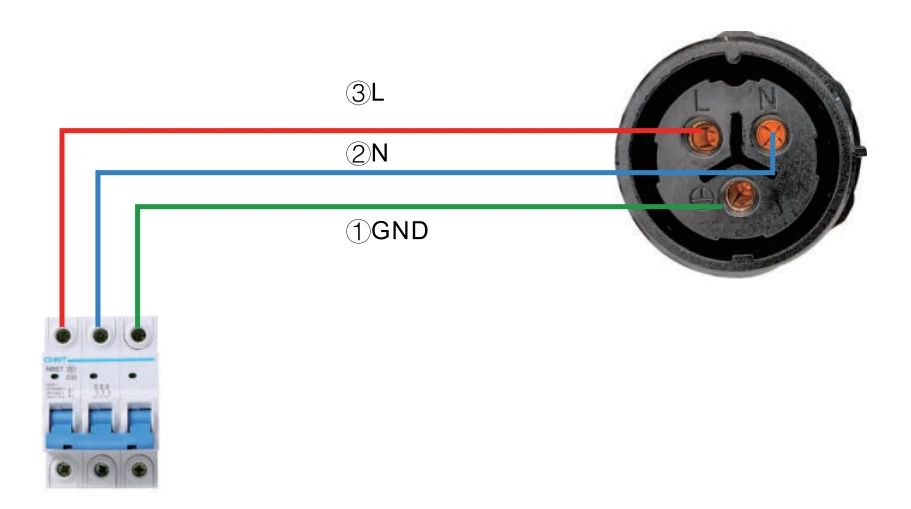
Note: It is recommended to use an AC circuit breaker with a rating of 30A. During installation, make sure all switches are turned off to avoid the risk of electric shock.
- Step1: Take out the battery system with Fuma wheel, then place it flat and steady on the ground where it needs to be installed, and adjust the Fuma wheel to a non-sliding state.
- Step2: Take out another battery system (if have) and inverter from package
- Step3: Fix another battery system (if have) and inverter on the present battery, make sure the inverter is on the top.
- Step4: Connect PV cable according to the terminal on the inverter.
Remark: Inverter Terminal Instruction

Step 5: Connect AC input cable according to the terminal on the inverter, firstly GND", then"N", last"L"
Step6: Turn on the power. Firstly turn on all the battery system, then press the inverter switch button. The LCD screen shows a complete link diagram, indicating that the system is in order (see below pictures).

Emergency Response Procedure
* When the ESS operates abnormally, the inverter, battery, and all load switches must be turned off first.
* If the battery system leaks electrolyte, avoid contact with the leaking liquid or gas. lf exposed to the leaking material, take the following measures immediately
* Inhalation: Evacuate contaminated area and seek medical attention.
* Eye Contact: Flush eyes with running water for 5 minutes, then seekmedical attention.
* Skin Contact: Wash affected area thoroughly with soap and water and seek medical attention.
* Ingestion: Induce vomiting and seek medical attention.
* In the event of a fire, please do the following:
Equipment combustion: lf the fire is controllable and personnel are safe, please use Novec 1230, FM-200 or dioxin fire extinguisher to put out the fire. lf the fire is uncontrollable, do not try to put it out. When the battery is heated to more than 150℃, it may explode. Evacuate personnel immediately to ensure life safety.
Fire near the equipment: lf it is safe, firstly disconnect the battery system circuit breaker to shut down the power charging. Then immediately extinguish the fire and evacuate personnel.
Daily Maintenance
* Cable Inspection: Check whether the wire connection is loose, aged, damaged, or falling off; check whether the cable terminals are loose or overheated; and the ground connection is good or not.
* Equipment Inspection: Check the battery system equipment for failure or damage every 6 months. When the system is running, check whether there is any abnormal noise in any part of the system. Check the battery voltage, temperature and other parameters. Check whether the equipment parameters are normal when the system is running.
* Equipment Cleaning: After using the equipment for half a year, the filter cotton on the left side of the ventilation needs to be removed, cleaned, dried and reinstalled, and the warning and guidance signs must be clear and intact, and the on-site environment must be clean and tidy.
Quality Assurance
* If the product fails during warranty, please contact a professional to repair it.
* The product nameplate cannot be torn off; otherwise, warranty service will be void.
* The following 7 points are not included in the warranty scope. If the customer requires repair, they should pay for the maintenance
service.
* The equipment is damaged during transportation, which is not arranged by our company.
* The equipment has been improperly installed, reinstalled, or used.
* The equipment operated in harsh environments.
* The malfunction or damage was caused by installation, repair, modification, or disassembly.
* Repaired by non-professionals.
* By using non-standard accessories.
* Damage caused by unexpected natural factors.